Unifying Map and Landmark Based Representations for Visual Navigation
|
|
University of California at Berkeley
|
|
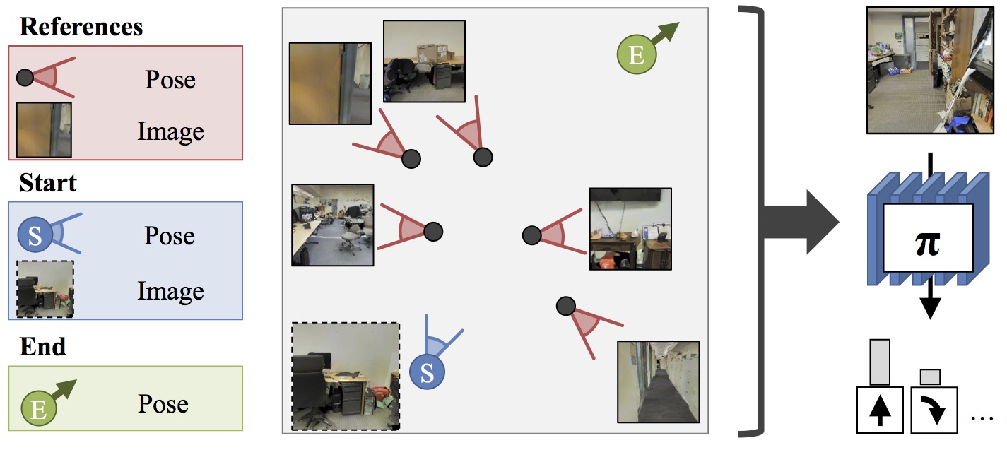
Problem Setup: Given
a set of reference images and poses, the starting image and
pose, and a goal pose, we want a policy π that is able to
convey the robot from its current pose to the target pose
using first person RGB image observations under noisy
actuation.
|
This works presents a formulation for visual navigation that unifies
map based spatial reasoning and path planning, with landmark based
robust plan execution in noisy environments. Our proposed formulation
is learned from data and is thus able to leverage statistical
regularities of the world. This allows it to efficiently navigate in
novel environments given only a sparse set of registered images as
input for building representations for space. Our formula- tion is
based on three key ideas: a learned path planner that outputs path
plans to reach the goal, a feature synthesis engine that predicts
features for locations along the planned path, and a learned
goal-driven closed loop controller that can follow plans given these
synthesized features. We test our approach for goal-driven navigation
in simulated real world environments and report performance gains over
competitive baseline approaches.
|
|
Paper
|
|
|
Unifying Map and Landmark Based
Representations for Visual Navigation
Saurabh Gupta,
David Fouhey, Sergey Levine, Jitendra Malik
arXiv 2017
arXiv /
bibtex |
|
Visualization for path following.
We present video visualization for the path following experiment
presented in the main paper. We restate the experimental settings here.
Path signatures are computed based on a random set of 40 images from
the environment sampled in a region of size 32m x 32m around the agent.
Goal locations are sampled to be within 32 and 36 time steps away. The
agent is run for 60 time steps.
Pieces of the
visualization:- Robot Camera view: As the agent moves, its
view is shown in the large plot on the left. The time step and the
value of ηt (eqn. 9) are shown
above.
- Overhead view: We visualize the overhead map in
the subplot on bottom right (free space shown in white). The agent
does not have access to this map. The location of reference images
are shown with green arrows. The
robot's starting position is shown with a blue circle and the goal location is
indicated by the blue star. The
planned trajectory is shown as a blue line. The executed trajectory
is visualized as a red
line.
- Path view and Memory: The two subplots on
the top right show: (1) the actual image on the planned path
corresponding to that time-step (the agent does not have access to it),
i.e., what the agent would see if the plan could be followed exactly;
and (2) the inferred relevant visual memory, i.e., the reference
image being focused on that the agent uses to derive signal at that
point in the plan. The location of the current relevant visual memory
is also visualized on the map with the magenta arrow.
The whole video: We first show the
map, reference image locations, then the start/goal pair. Then we show
the planned route and what was actually done. This defines the setup
of the problem; we then let the robot run. As the robot runs, we show
what it sees, what the plan says it should see, and which reference
image its policy is focusing on at each timestep. Whenever there is a
noisy action, it is marked with an X on the map. Note that the visual memory is retrieved from
a plausible location on the map that has visual overlap with the view
from the current location on the plan. Additionally note that the
pointer along the plan moves in rough synchronization with the agent's
actual location.
|
How Does It Work? |
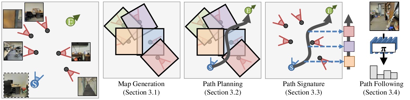
Our method consists of four parts.
- Map generation: given a set of reference images and their locations, we infer a map that can be used for planning.
- Path planning: given a map, we learn to plan a sequence of actions that will take the agent from one pose to another.
- Path signature generation: given a map and a plan, we infer a signature of what the agent should see along the trajectory. This is
used to compensate for noisy actuation.
- Path following: we learn a policy that can follow a path signature.
|
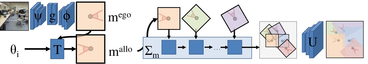
1. Map generation
Given a set of images, we pass it through an encoder ψ,
fully-connected layers g, and decoder φ to produce a map in an
egocentric view. The egocentric view is passed through a transformer that
uses the camera's pose to map the egocentric map to an allocentric
coordinate frame. Given a collction of all of the maps, an accumulation
function Σ assembles all the information from the allocentric maps.
These maps are finaly passed through a series of deconvolutions U,
producing a map of the space in an allocentric coordinate frame.
2. Path planning
Given a map, we can then plan in the map using a value iteration network.
This planning is learned jointly with the mapping, enabling the mapper to
make meaningful extrapolations about parts of the space that it has not
directly observed.
|
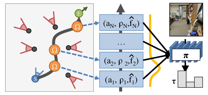
3. Path signature generation
Given a map and a plan, we want to use observations to help the agent
execute the plan under noisy actuation. We do not have observations for
the entire sequence, so we learn to synthesize features at locations that are unobserved. These
are used by the subsequent part of the agent. This path signature encapsulate the information that
the agent needs to perform the navigation tasks.
4. Path following
Finally, a module executes the plan expressed as a path signature. We
implement this using a soft sequential attention. The network softly
attends to the path signature to obtain a synthesized observation. It
uses this observation, along with what it can see, to determine an
action, update its state, and figure out what to attend to next.
|
Acknowledgments
| This work was supported in part by Intel/NSF VEC award IIS-1539099, and the Google Fellowship to SG.This webpage template was borrowed from some colorful folks. |
|